decambered rear springs Spax shocks all round and 2.8 vented disks. Fitting the power steering seemed like the logical next step,
I'm not to sure I would have done this mod on its own.
The parts needed are:-
Pinto Engined Granada or Transit parts:
a. Power steering pump
b. Combined pump and alternator bracket
c. Dual belt water pump pulley
d. Dual crank shaft pulley
e. Dual belt alternator pulley or complete alternator.
2.8 Capri parts:
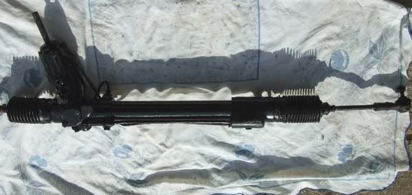
a. Power steering rack
b. Power steering hydraulic pipes
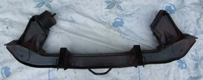
I also acquired a pinto engined Capri cross member to fit the 2.8 rack to. As there's a fair bit of cutting and fabricating I thought I'd practice on this to see if it was possible first rather than cutting up mine and have it all go wrong
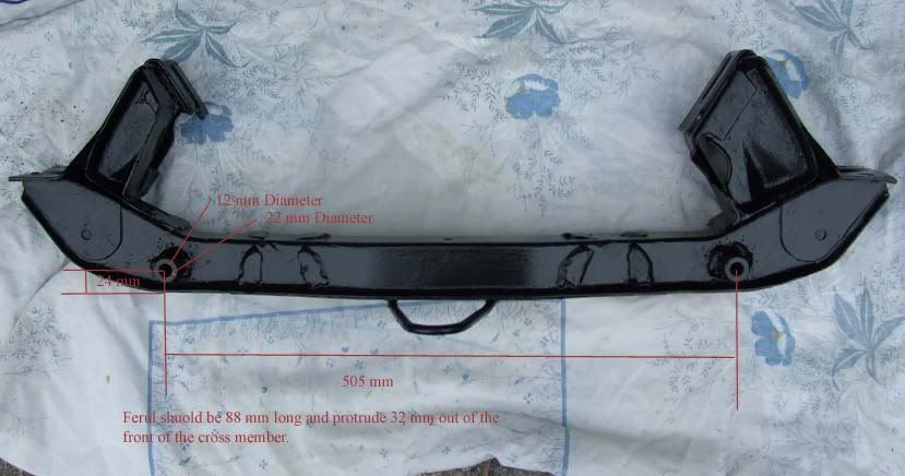
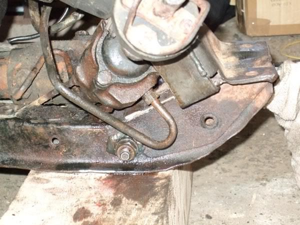
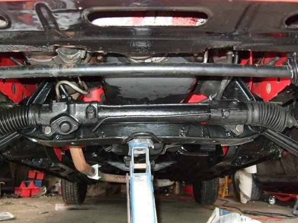
The first step is to cut off the original steering rack mounting brackets on the cross member and weld in new mounting points for the
2.8 rack shown in the following photo. The measurements were kindly supplied by Privateer on Capri Power which I would otherwise have had to get from a 2.8 Capri. The mounting points are made from two steel rods 88mm long 22mm diameter and with a 12mm hole for the
mounting bolts. The cross member has to drilled to take these and then the rods welded in at the front and rear.
Next the drivers side up stand on the cross member has to be cut back as the new rack has a much wider surround on the input shaft.
I then welded plates and gussets to the remaining part of the up stand to strengthen it.
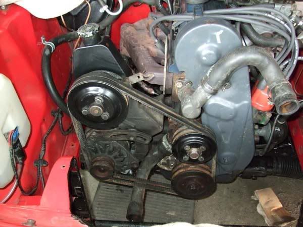
I swapped the single pulley on my alternator for the dual Granada one but if you know the Granada one works you could just use it complete.
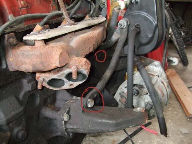
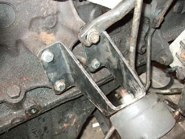
There's a couple of steadying brackets on the pump one of which originally bolts to the Granada/Transit engine mount. I was originally going to weld an extra mounting point on the pinto engine mount for this to connect to but in the end managed to cut a notch out of the pinto mount, use the longer Granada bolts (Privateers suggestion) and twist the bar slightly to fit.
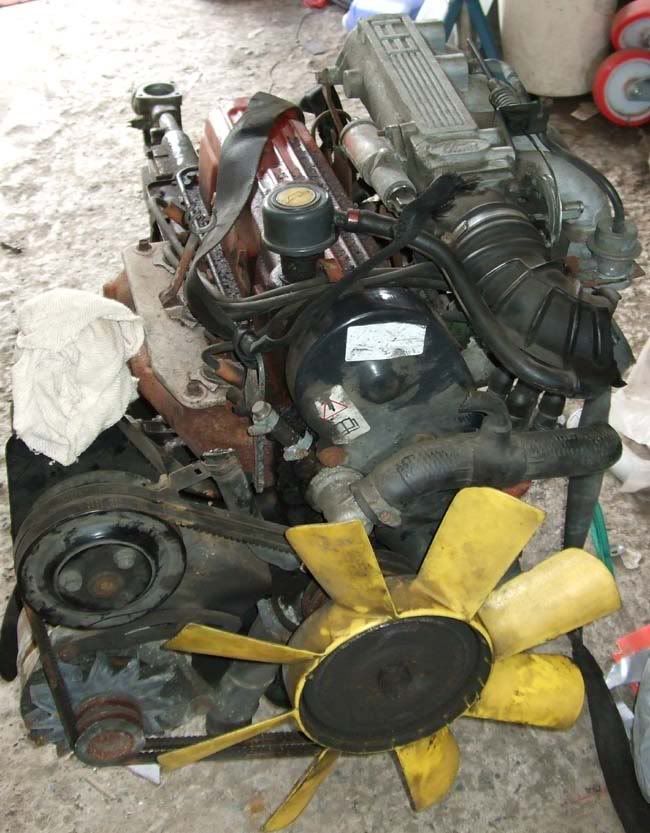
I then set it all up on the spare engine to check it all fits.
Next I removed the cross member. (Obviously the engine will need to be supported as well as the car when doing this)
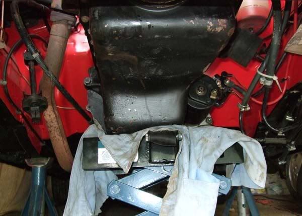
And then the viscous fan, alternator crank pulley and water pump pulley.
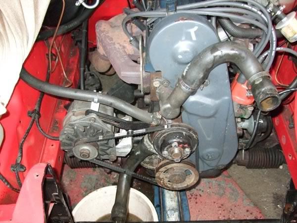
The new stuff is pretty well all just bolt on. I did find though that the fan hits the crank pulley bolt as its now further out. You could use the Granada fan but this wasn't an option for me as the one I had was knackered. I'll fit an electric fan later.
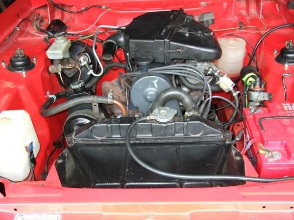
A couple of other points are the bottom radiator hose needed lengthening as it was now fouling on the new fan belt, and the top heater hose was to short as it was now routed past the power steering pump. I used a couple of short pieces of 35mm and 15mm copper tube for this. To stop these pipes blowing off under the pressure I've soldered 35 and 15mm olives from compression fittings onto them to create a sort of shoulder and then used jubilee clips.
The power steering pipes have to be shortened and because of the high pressures involved the ends will need flaring out and crimped joints made where the rubber hose joins the steel pipes. Being a plumber / heating engineer I have the facilities (Used on LPG pipes) to do this but I think some motor factors can make up the connections while you wait.
After toping up with Hydraulic fluid the engine can be started. To clear any airlocks hold the engine to about 1500 rpm and slowly turn the steering wheel from lock to lock until bubbles stop appearing in the fluid reservoir. You will probably have to top up a couple of times.
As you have changed the rack the tracking will need re setting you can set this up well enough to get you to a garage by measuring the front wheels at stub axel level from the back inside wheel rims to rims and then across the front of the wheel rims to rims. The measurement should be equal (Zero toe in) or up to 7mm longer at the rear measurement (7mm toe in).
To return to my home page: Click here